|
| ||||
| HV Power Application Newsletter #14 (March 2015) | ||||
| Commentary: Cigre SEAPAC
|
||||
|
We are gearing up for the Cigre SEAPAC Conference and Exhibition next week in Sydney where, as an exhibitor, we aim to show a range of new features and new products from our supplier A.Eberle. This will provide you with the ideal opportunity to see and interact with the products and their support software. While our focus will be on highlighting some new features, we are always happy to discuss any specific applications or questions you may have. SEAPAC is an ideal forum to network with engineers from the power utility sector with a very relevant interest, protection and automation! Geoff and myself will be in attendance at Dockside Cockle Bay (Darling Harbour) on 17th and 18th March and look forward to seeing you there. Please feel free to call us in advance if you already have some really curly questions we might need to research beforehand. We hope to see you at SEAPAC! |
||||
| Power Quality: Single Phase Power Quality Measurements - PQ-Box 100 & PQ-Box 200 | ||||
|
Recent versions of firmware support the single phase measurement of power quality with our popular PQ-Box 100 and PQ-Box 200 portable anlaysers. By selecting ….Configuration….System = ‘1-wire System’, this essentially turns off voltage channels L2 & L3 and current channels L2 & L3. The PQ-Box 100/200 ignores these inputs, so:
While this new option does reduce the file size of the recordings, it’s not really an issue with the PQ-Box 100/200. The PQ-Box 100 is now delivered with 2 GB of memory, so even recording with all input channels turned on, the memory size allows many months of data to be logged (based on EN 50160 standard settings).
|
||||
Power Quality: WinPQ mobil version 2.2.4 is now available for download |
||||
Please be advised that WinPQ mobil version 2.2.4 has now been released. Both 32 and 64 bit versions are available. Download size is approximately 140 MB. Included in these downloads is the latest firmware and manual. The latest software update includes several notable features:
Check out our Technical Library write-up if you are interested in the full details of the new features, or simply download (free) the new version from here
|
|
Voltage Regulators and Power Quality: Optional 5-year product warranty from A.Eberle | ||
|
||||
Voltage Regulation: Choice of Comms ports on REG-DA’s |
||||
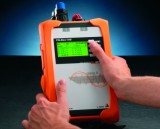
You may be aware that REG-DA (and REG-D) can be ordered with a USB port for COM1 connection (for front panel WinREG connections/settings etc) rather than the standard RS-232 connection. Below are photos of a recently delivered unit. This is what you can see: Photo 1:

Photo 1. A.Eberle REG-DA with USB and assorted PED options. Photo 2:
 Photo 2. A.Eberle REG-DA with COM3 fibre port for connection to remote I/O box. | ||||
Voltage Regulator: REG-D/DA Recorder Upgrade ‘S2’ |
||||
Option S1 has been available for quite some time, and is a very useful diagnostic tool for REG-D/DA Voltage Regulating Relays, adding a three channel recorder. The S1 option allows up to three selectable analogue values to be recorded (at minimum scan time of 1 second), in addition to tap position. Included is PC software ‘Collector’ and ‘REGView’ for extracting and displaying this information in a strip chart fashion. Regulators shipping since late 2013 have included increased on-board memory (100 MB) and support an S1 or S2 option. S2 provides the ability to select up to 64 analogue values to be logged. We recommend you consider the S2 option with your next voltage regulator order! | ||||
| Compensated Networks: Earth Fault Detection | ||||
|
Following on from our successful implementation of A.Eberle EOR-D substation level earth fault detection relays, several Swedish Neutral GFN customers in New Zealand have placed orders for EOR-3D earth fault detection relays for use at feeder level. The EOR-3D is both an earth-fault relay and short-circuit passage indicator in an extremely compact housing. In particular, the advantages of different fault detection/location methods can be combined, depending on the fault characteristics. For the first time prioritisation, and thus weighting, of the different fault-locating procedures is possible.  A.Eberle EOR-3D Earth Fault Detection Relay for compensated power systems. The implementation at feeder level requires very accurate voltage and current inputs as the earth fault currents on compensated systems are extremely low. This has been solved by the use of overhead-line-mounted polymer housing combined current and voltage sensors. They are easy to mount and provide 'plug and play' connection with the EOR-3D relay. 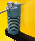 Post mounted voltage/current sensor - replaces a normal insulator. Often these devices can be located at an established recloser location to use the existing infrastructure of LV supply and communications. However, we also have a solution for standalone applications, with the EOR-3D relay mounted in a stainless-steel weatherproof enclosure complete with battery supply, solar charger and radio comms. If Ethernet communications are available at the device, remote engineering, logbook records and download of Comtrade fault records can also be supported, allowing engineering staff to remotely access the device. Of course, DNP3 (serial or IP) SCADA comms is also supported. With 4 GB of internal memory, a substantial quantity of records can be stored for eventual analysis. The new A.Eberle toolbox software provides a very powerful, yet simple, tool for engineers to understand what is happening at the remote location, and gives a wealth of information (previously unavailable) for analysis of the fault and network conditions. |
||||
| Voltage Regulators: The internal algorithm! | ||||
|
As an aid to our customers, HV Power is writing documents covering the basics of voltage regulation using A.Eberle’s REG-D & REG-DA’s. These describe (in Australian English!) the internal operation of the REG-D/DA. These guides are ideal for those wanting to know more about the settings and operation of the regulators. Access our website Technical Library now, to download:
Watch out for our future newsletters as we have more coming over the next few months. |
||||
| Power Quality: Measuring superimposed DC voltages | ||||
|
The PQ-Box 100 (and 200) Power Quality Recorders are true RMS recording devices and subsequently have the ability to measure and record the DC component of an AC+DC waveform. The units can be used for ‘just’ DC voltage measurements, for example, where customers use the PQ-Box 100’s '0.1 % accuracy' to very accurately set a 24 Vdc supply. After logging data with the PQ-Box 100/200, WinPQ mobil software can be used to display over 360 different values including ‘U eff’ (True RMS value of AC+DC component) and ‘DC Voltage’(the calculated DC component of the ‘U eff’ value ).The 'DC Voltage' trace is derived from the calculated DC component of an AC +DC waveform and can be displayed in units of ‘Volts’ or as a ‘percentage’ of the total RMS value.  Measuring DC offset with PQ-Box 100 & PQ-Box 200. If you have an application where measuring DC components is of interest, we would be interested in setting up some field measurements. Perhaps you are interested in:
A 'DC Current' value is also recorded by the PQ-Box 100, which is the current equivalent to that of voltage described above. 'Hall-effect' DC measuring current clamps (200 mA to 60 A or 0.5 A to 600 A), or 2 A current shunts are available, which are suitable for measuring AC+DC, so true RMS current and DC component measurements are possible. DC measurements are NOT possible when using the standard mini-clamps and Rogowski coils, as these are AC coupled. For further information, please refer to the Power Quality section of our website Technical Library (PQ Box 100 Hints and Tips #11). |
||||
| In Australia call 1-800 172 120 | www.hvpower.com.au ABN: 62 113 118 536 | |||
|
Copyright 2015 HV Power Measurements and Protection Limited. This newsletter is authorised by HV Power Measurements and Protection Limited. See our website for contact details: www.hvpower.com.au. | ||||